Based on the calculation of the “Work-and-Go” I would like to present the advantages of simulations of large assemblies with SIMSOLID.
The classic finite element method is a proven solution when complex mechanical problems need to be calculated.
All you need is the geometry, material data and loads. Then you select your preferred FEM software, import the geometry and assign the material data to the individual parts.
The biggest step is networking, here it is decided how exact the results of the calculation will be and how long you have to wait for it. Often the geometry is greatly simplified in order to have to calculate fewer elements. This often makes sense: If you save half of the elements, for example, the calculation time will shrink to about a quarter and you need less RAM.
This may lead to temptation to simplify assemblies to far in order to get results faster!
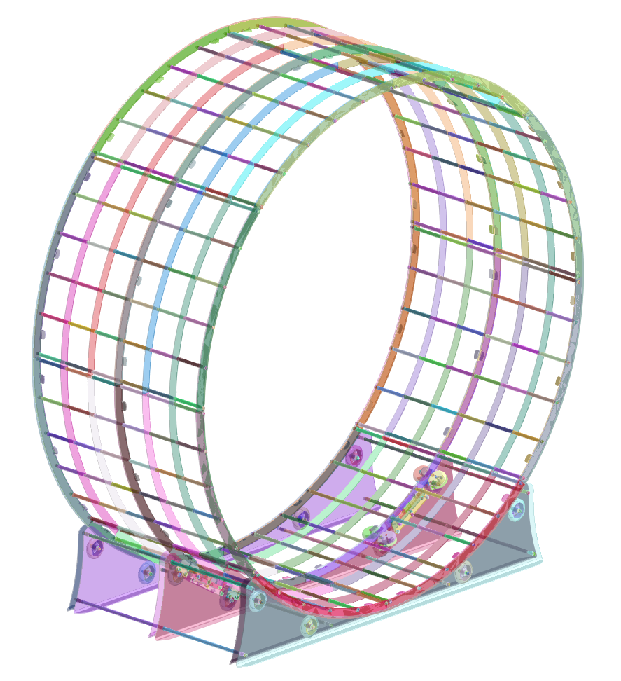
But how to simplify an assembly which has 1000 individual parts with approx. 3500 contacts? Certainly every calculation engineer advises you not to calculate such an assembly on your laptop.
With SIMSOLID, very large assemblies with many contacts can be easily calculated. This works because this software goes a completely different way than “classic” finite element programs. Instead of splitting complex components into many small elements, SIMSOLID analyses the 3D data directly and uses special element formulations to calculate the geometry efficiently. (further information: https://www.simsolid.com/white-papers/)
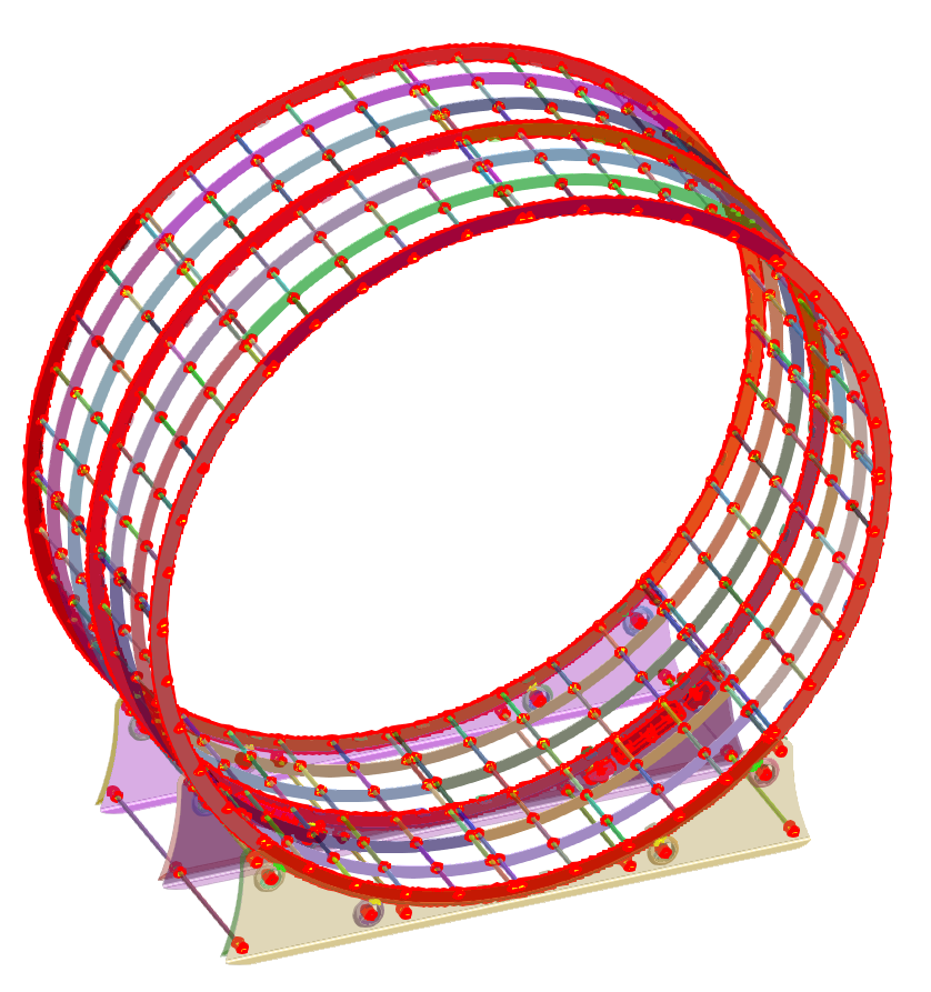
Entering all boundary conditions is hardly different from common FEM programs. Material data can be defined for each part, contacts between several parts can be searched for and defined and external loads can be specified.
In this example, the following loads have been defined:
- Fixed and sliding bearings on the bearing surfaces to the floor
- The bolt preload that holds together and stabilizes the construction
- The individual load in the middle of the walking surface which corresponds to the weight of a person + high safety factor 🙂
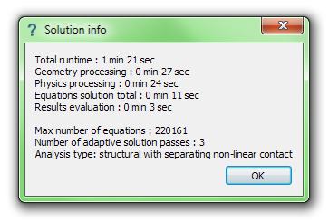
If everything is defined correctly you can start the calculation. Unlike the classic FEM method, you don’t have to wait long for the solution:
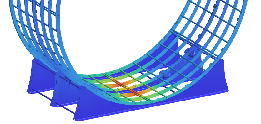
As a result, the total deformation can be displayed: (Attention: The deformation is displayed with a multiple amplification)
In addition, the mechanical stresses in the components can be displayed. In the following picture you can clearly see how the pipe struts behind it are pretensioned by tightening the screws:
how this may lead to temptation to simplify assemblies to far?
Normalment mai m’ha agradat llegir articles als blocs
però per aquest bloc vull dir que aquest escrit realment em va obligar a provar-ho!
El teu gust per l’escriptura m’ha sorprès.
Gràcies, molt bon article.
Thanks for information Universitas Telkom
What challenges or limitations did the author face while preparing this article?